2021 ~ ongoing · DIY multi-touch interface for writing/drawing tools with contact mic
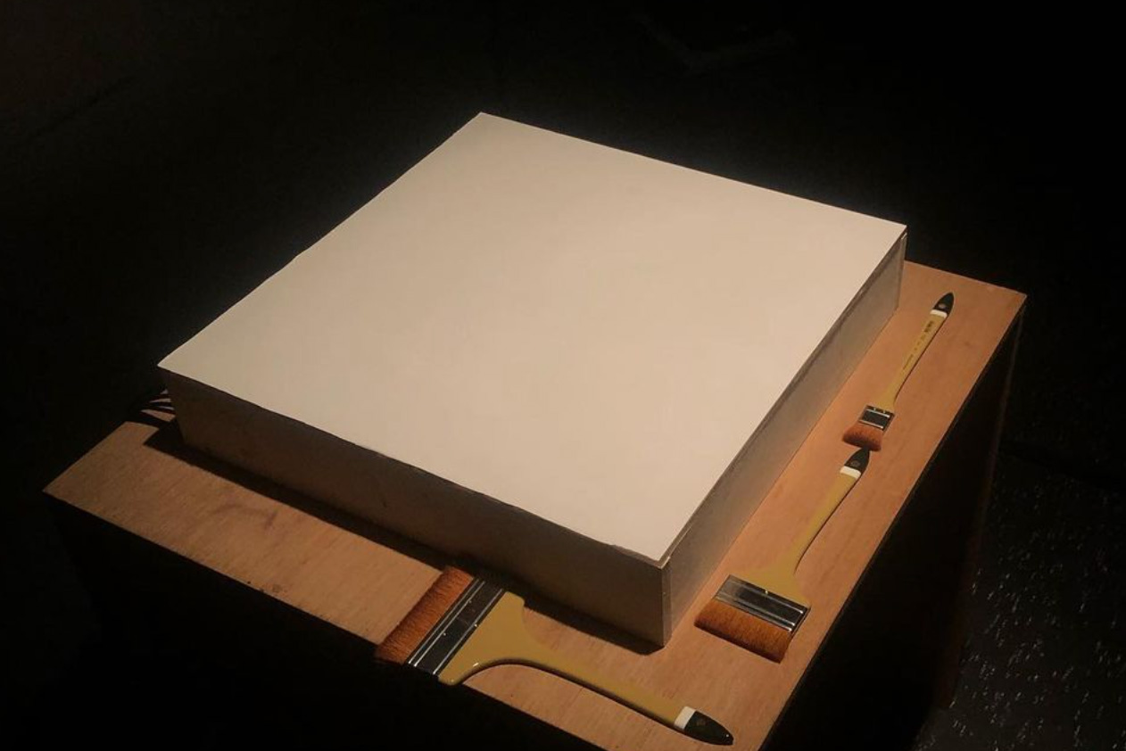
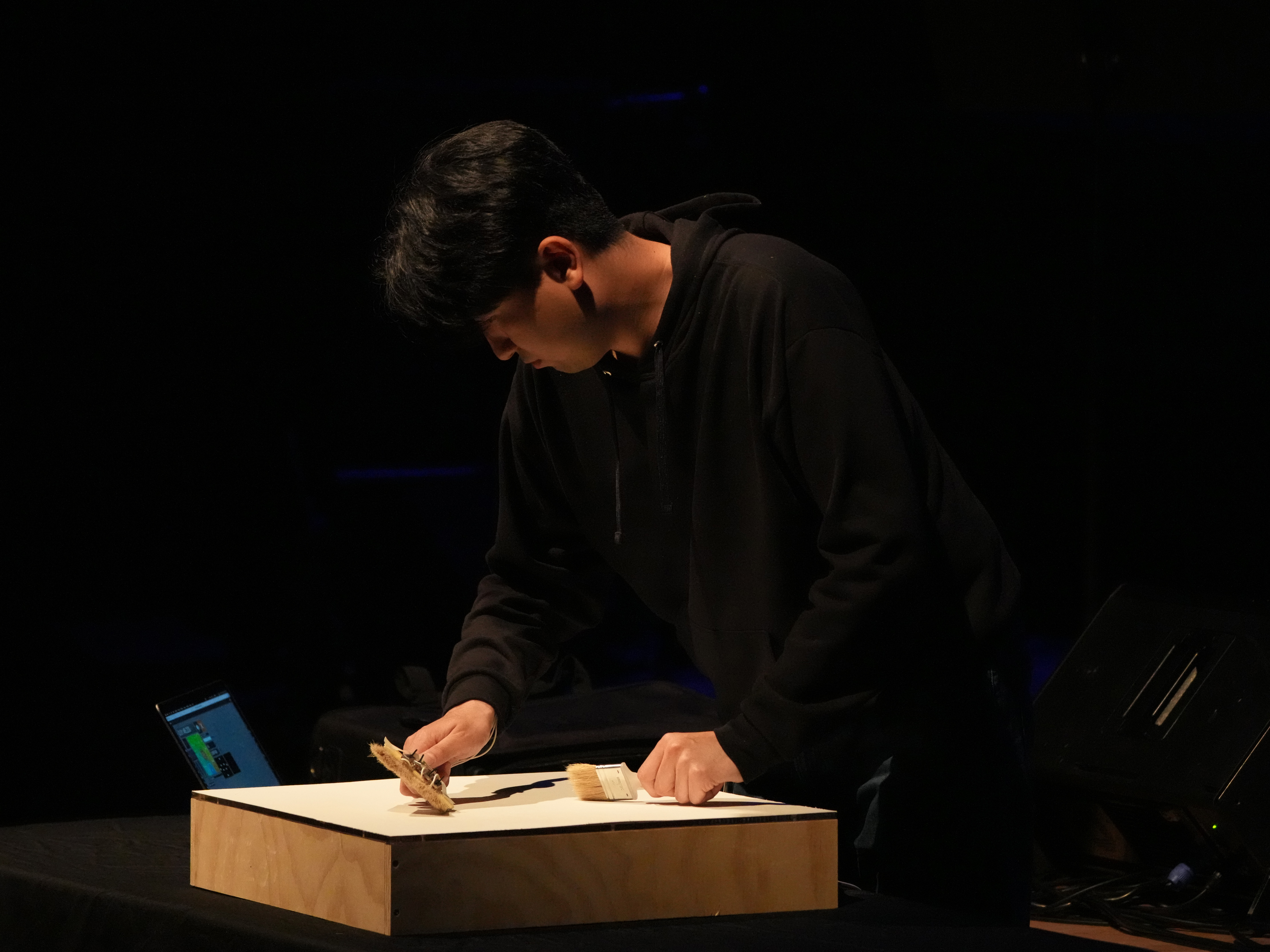
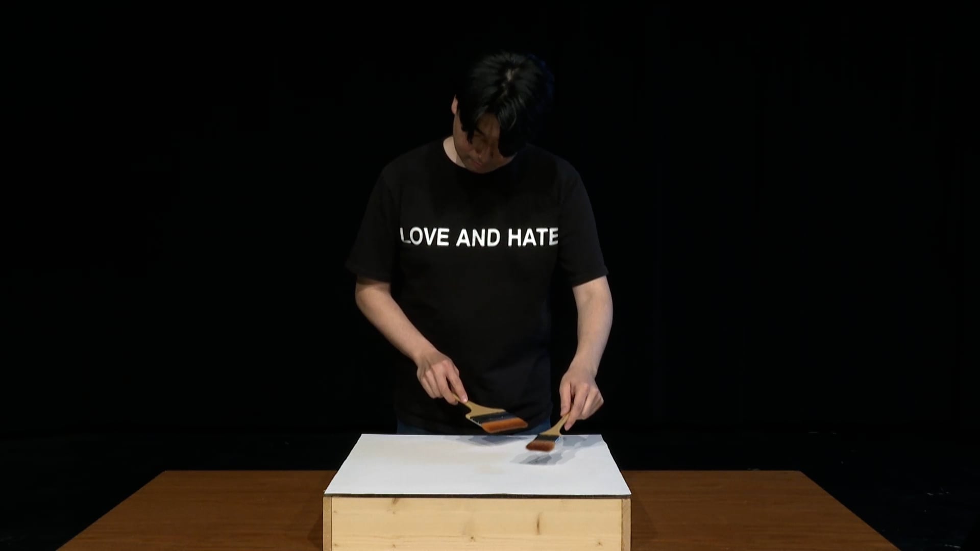
The Brushing Interface is a novel musical instrument that detects the movement and pressure of drawing and writing tools on its surface. Its exterior wooden structure is topped with an acrylic sheet housing a sensor grid and a piezo microphone. This assembly is covered with paper, providing the surface where the performer draws, brushes, or writes during a performance. The core circuitry posits inside the body of the instrument.
The key technical engineering involved in this project was implementing the pressure sensor grid using a custom, DIY approach. Commercial FSR sensors cost around $5 per 2 cm square, totaling over $1,000 for a full set. This was obviously not economically feasible. Furthermore, using proprietary sensors made it impossible to customize their shape and size, imposing a significant constraint on the creative process.
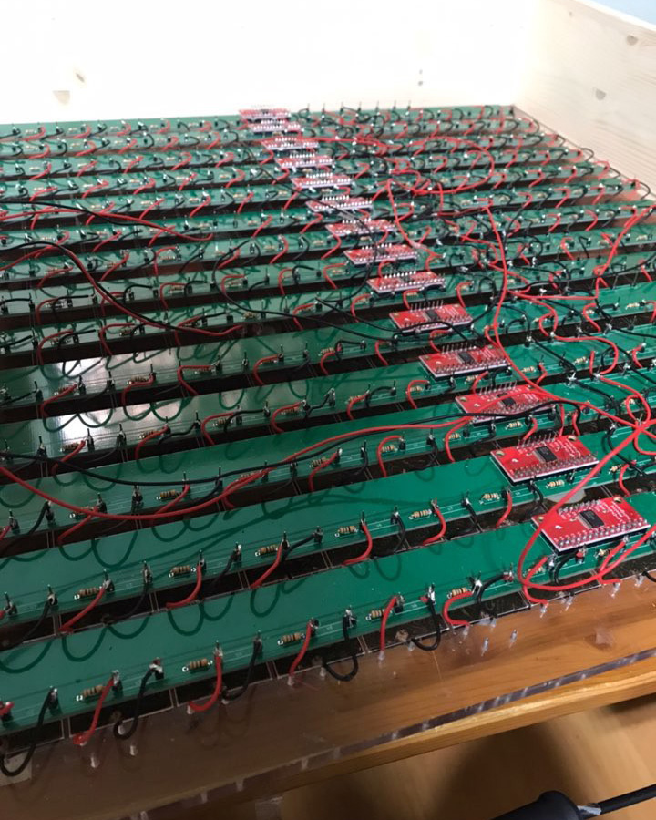
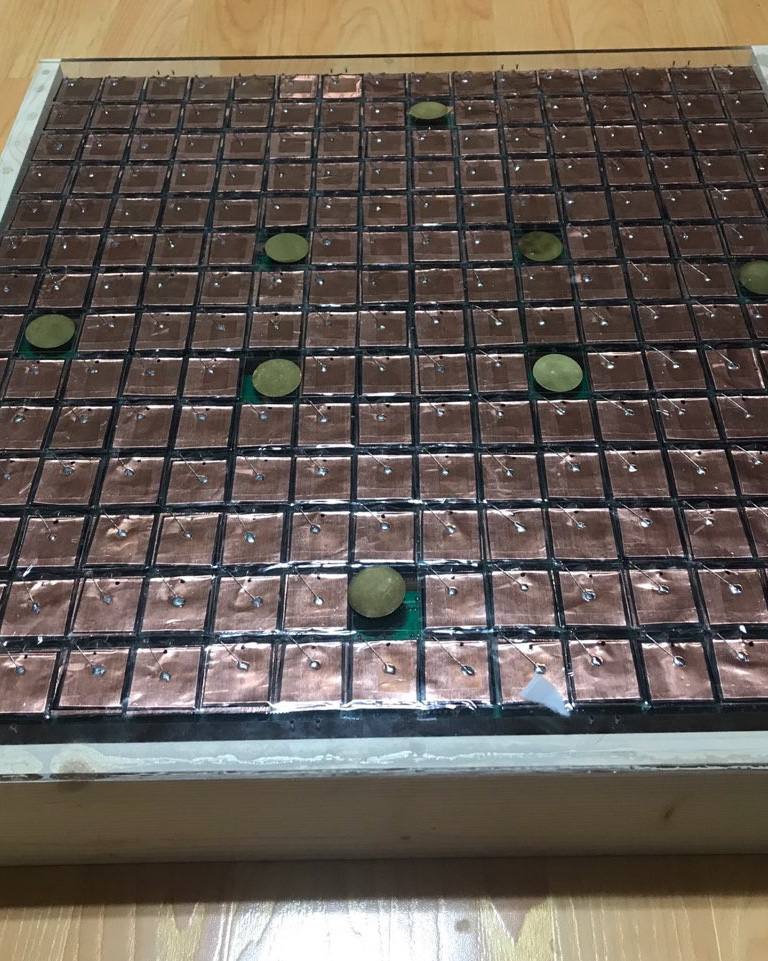
PCBs mounted on the inner part of the instrumentTop surface of the instrument with the paper removed
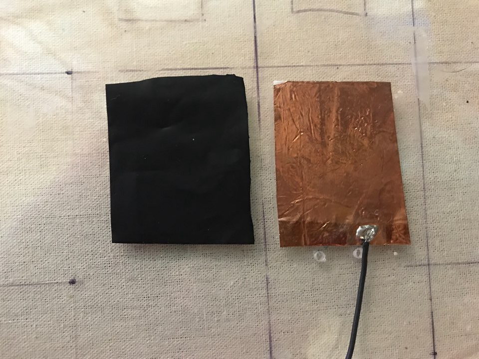
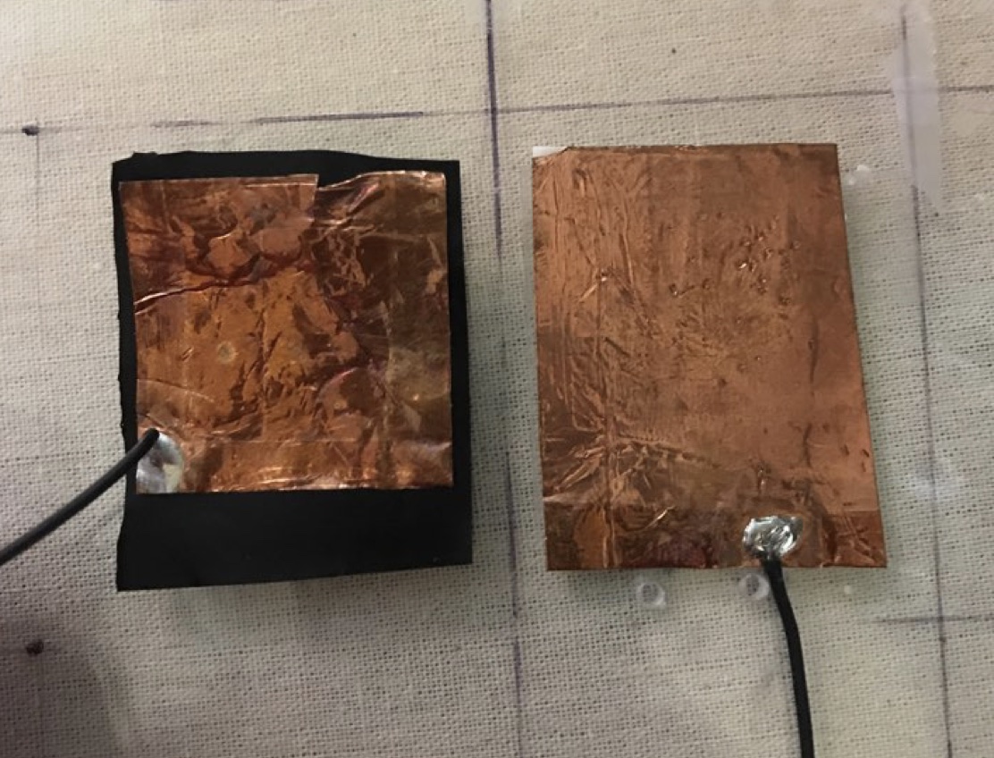
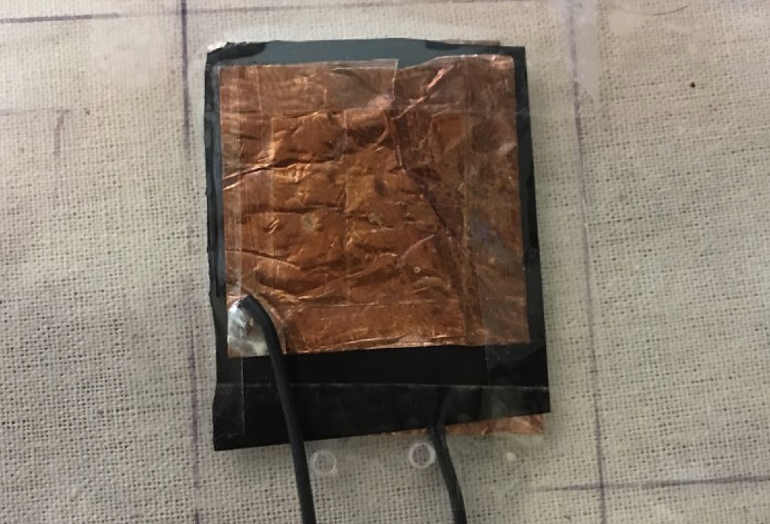
Therefore, a critical first step was to build a reliable and affordable FSR sensor from scratch. FSRs (Force-Sensitive Resistors) consist of a flexible resistive layer between two conductive layers; pressing them brings the conductors closer together, lowering resistance. Existing DIY literature showed that copper tape worked well for the conductors, so the main goal was finding an appropriate piezoresistive material. Through experimentation, Velostat emerged as the ideal material due to its low price ($5 for a 30 cm² sheet) and ease of handling. The final sensor was constructed by sandwiching a layer of Velostat between folded copper tape to achieve double-sided transduction.
Velostat (left) and bottom layer copper tapeThe upper layer copper tape on the Velostat (left) tapeThe upper layer copper tape and Velostat taped on the bottom layer copper tape
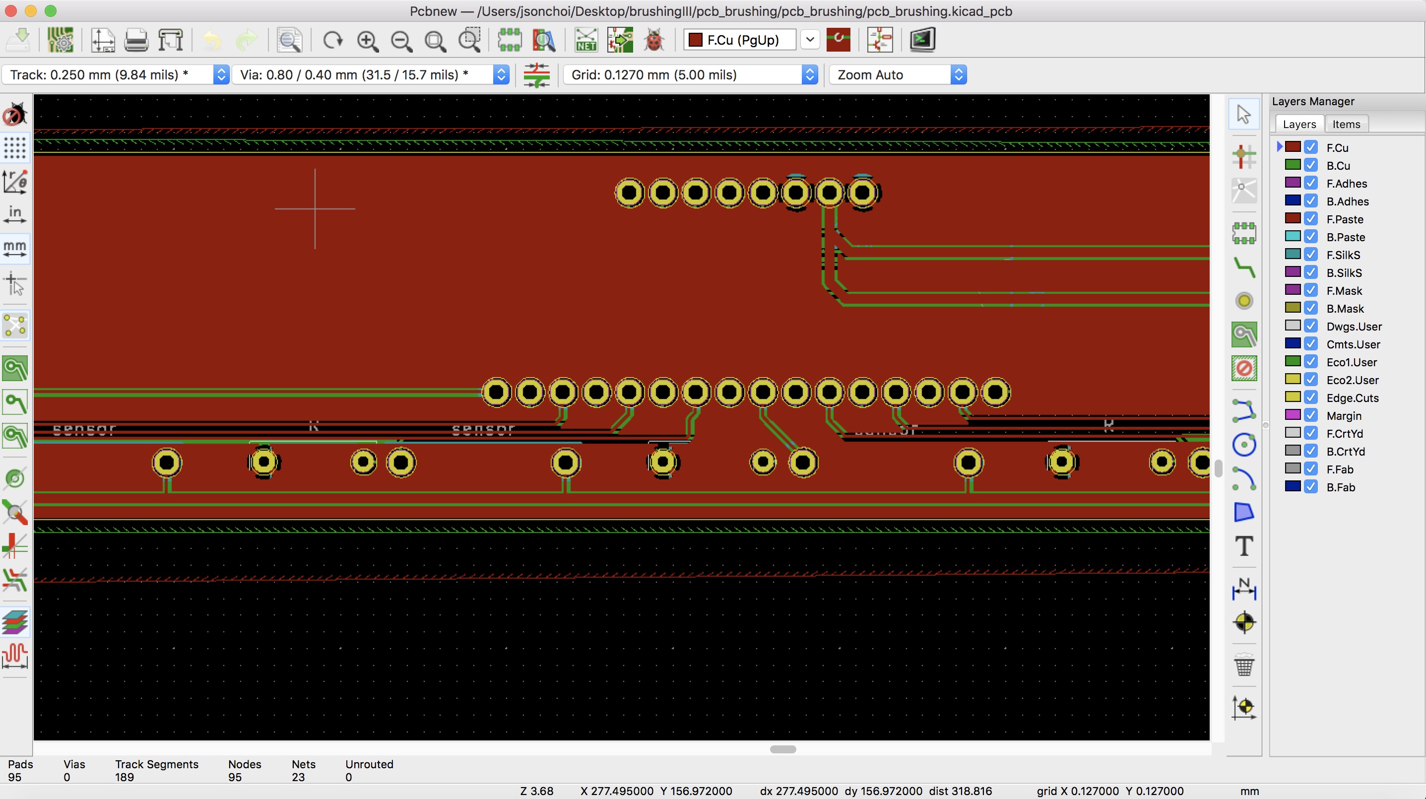
This sensor design proved to be extremely affordable, reliable, and sufficiently sensitive. The next challenge was connecting over two hundred of these FSR sensors to a single microcontroller. Because most hobbyist microcontrollers have at most 20 analog inputs, multiplexing was required. Specifically, I used the CD74HC4067 16-channel multiplexer (via SparkFun breakout boards). A Teensy microcontroller was selected to handle the sensor data due to its high processing power and fast sample rate, ensuring smooth, real-time data acquisition across all sensors. This allows to send all 216 sensor data through serial to the Max patch for real-time mapping. Finally, to ensure circuit reliability and clear organization, a custom PCB was designed in KiCad and professionally fabricated.
PCB layout for the sensor grid, designed in KiCad
In terms of audio, it picks up friction between the writing/drawing tools and the paper through 8 piezo microphones, which is sent to the Max patch through an audio interface. Inside the Max patch the sound is processed in real-time through the mapping with the pressure sensor data input based on the composition of the piece.
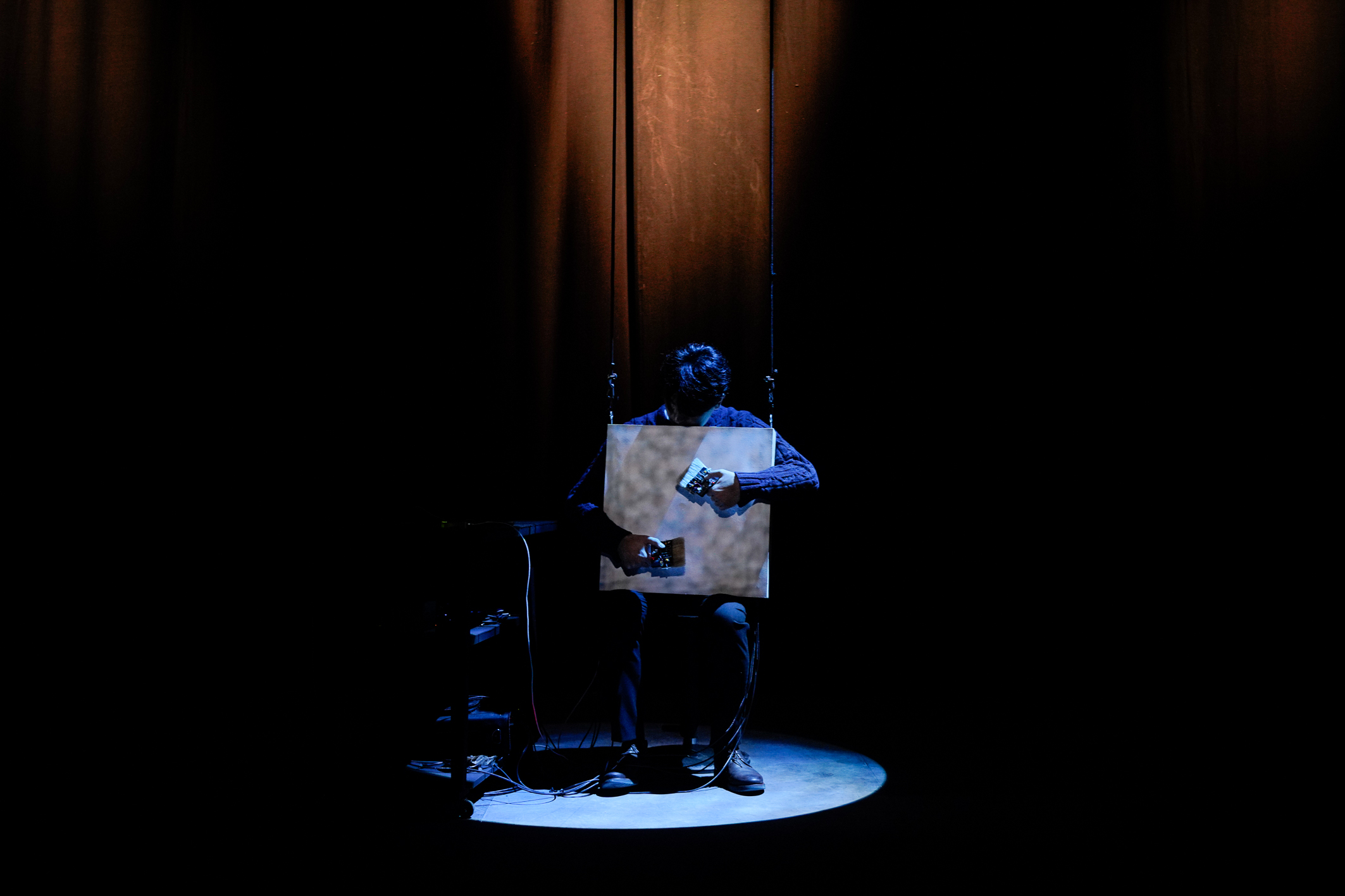
AEIOU
2026. Solo performance for Brushing Interface and webcam, 6 minutes
AEIOU is a solo performance for Brushing Interface,
a self-made novel musical instrument, and webcam. This piece explores how the
cumulating drawing and writing forms a contrapuntal relationship with the sound in
live performance. The musical operation arouses with both the visual and aural elements,
which each of them framing each other. Furthermore, this piece/practice is not confined
to the moment of performance or the static work of composition, but instead incorporates
a holistic pursuit of novel musical instrument making through archival approach.
GitHub Link of Sensor Data Archive
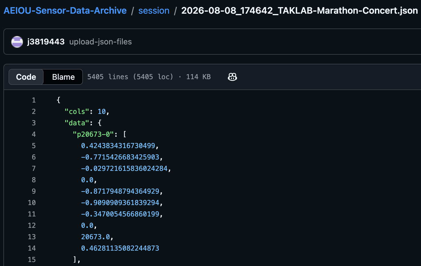
The sensor data json files are from the 14×16 grid of force-sensitive resistors
of my instrument, played with a writing or drawing tool. While playing, the system
measures position, pressure, contact area, and their rates of change, and retains
only those gestures sufficiently unlike anything already recorded. At the end of a session,
whatever was retained is written to session/ as a dated JSON file. The archive is never edited,
deleted from, or duplicated. At the start of each session, the instrument reads every file here,
keeps a proportion of each according to its age, and builds a k-d tree from the result. While
playing, each gesture retrieves its nearest precedent from that tree — a specific past moment,
not a category — and what I hear depends on whether I am repeating myself or departing from myself.
Files are append-only by convention, not by enforcement. A session that went badly is still a session.
The feature vector is fixed at eight columns. Adding a ninth would fork the archive, since points
of different widths cannot share a tree. Growth is expected to slow. As the archive saturates the
range of what I actually do, fewer gestures qualify as new. Points added per session, plotted over
years, is a measurement of my own repetition, and is arguably the more interesting document.
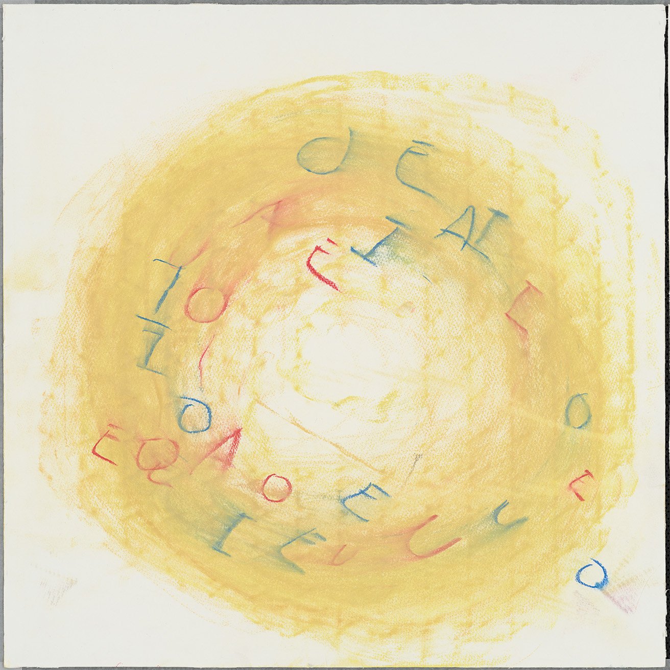
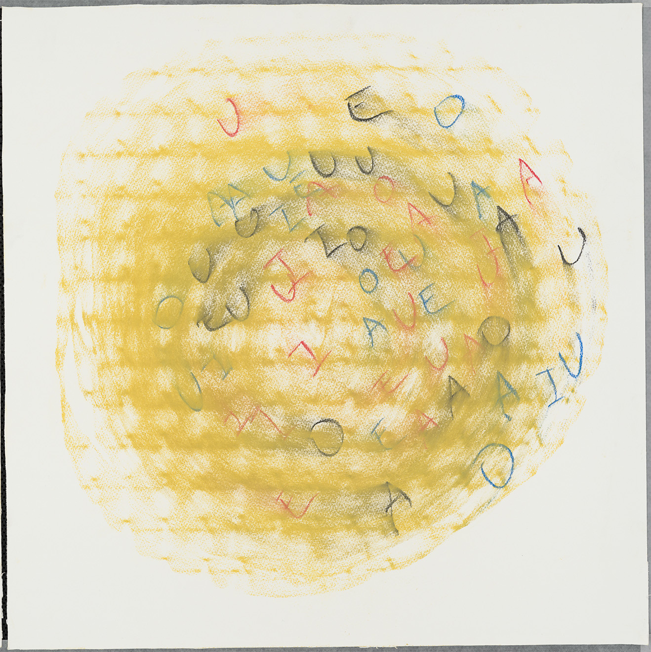
If the sensor data files are the digital archive, the drawings are the physical artifact,
treated as independent art works on its own. At the same time, it lives within my holistic
pursuit of novel musical instrument making, as an residue archive of my lutherie commitment.
Furthermore, these are also digitally scanned in professional level, which becomes another
visual-digital archive on its own.
This project was initially workshopped and premiered at TAK LAB from TAK Ensemble.
Also big thanks to Seth Cluett , Qiujiang Levi Lu , and the EPCT cohorts!
Scanned Image of Drawings
Drawing from the video documentation on August 25th, 2026 (2026)
Drawing from the TAK LAB Marathon Concert on August 8th, 2026 (2026)
Drifting
2022. Solo performance for Brushing Interface, 6 minutes
Video recording: EP Video editing and post production: Yeon Park Production engineer: Greg Palmer Audio recording assistant: Dan Serino Video recording assistant: Hayden Ngitngit
Drifting is a solo performance for Brushing Interface, a self-made novel musical instrument, in 8-channel audio. This piece aims to deliver the nuanced and sophisticated materiality of a brush through an intersection between sonic timbre and brushing gestures by creating a deep timbre space on a finite two-dimensional surface. The deep timbre space is constructed by timbre transfer from the brushing sound inputs and other realtime synthesis, which are mapped with brushing positions and machine-learning-based gesture detections (rbfi for position-based mapping and MuBu for machine-learning-based gesture detection).
As one of the earliest composition for the Brushing Interface, it acted as a valid proof-of-concept for the artistic potential of this instrument.
Free Improvisation using the Brushing Interface
Free improvisation
Performance at MATA Festival, Roulette Intermedium, Brooklyn, NY, 2023
This performance is a free improvisational performance that aims to transform the nuanced materiality of the brush and brushing gestures into a musical/sonic expression through mediated technology. For the performance, I use the Brushing Interface, which is a self-made physical interface that detects the position and pressure of the brushing gesture and its sound in realtime. The improvisation is aroused from my deep inter-relation with the interface as a builder and the performer, and my body acts as a central role in this creative process.
Brushing Improvisation – N°2
2023 · Solo performance for Brushing Interface, a self-made musical instrument · 17 min
Courtesy La Biennale di Venezia · Photograph by Andrea Avezzù
Commissioned by and premiered at La Biennale di Venezia 2023, 67th International Festival of Contemporary Music
Brushing Improvisation – N°2 is a semi-composed improvisation that translates the brush’s material subtleties into sound and explores its cultural perception as a foundation for musical form. The piece utilizes the Brushing Interface, a self-made musical instrument that captures the sound and movements of brushing gestures in real-time. The formulation of the piece came from my deep inter-relation with the instrument as a maker and performer, which my body acts as a central role in this creative process.
This piece emphasizes the translation of the brush’s material subtleties and gestures into sonic expression through specific mediated technologies. Also, it explores the cultural perception of the brush, employing it as a structural element for musical improvisation. This dual focus fosters a seamless integration of theatricality, gestural performance, and the interplay between composition and improvisation.
Performance Videos
Premiere at La Biennale di Venezia 2023, 67th International Festival of Contemporary Music